


At the beginning of year (2003), I exposed you my project of producing engine with renewable energy of water and electricity. In response to this approach, I had calculated the return on investment with the simple production of electricity, the production of water being his second added value.
In this file I include the principle of operation by adapting it so as to produce only water.
Thus I think of being able to reduce in absolute value the total cost of the installation, to make the project more independent of the investors, and to also meet a need much more local with respect to the consumers.
In short, I wish to carry out an installation profitable but rather directed towards the need for ten hearths a country in the process of development.
The average of the requirements out of water for a African family is 5 to 7 liters of water/day.
It is necessary to know that the water content in gram/m3 is identical the day and the night, however the night being fresher, the percentage in moisture (or relative humidity) is higher.
Also, for preoccupations with a total output of the installation, we will seek to produce water, the night.
We will accumulate solar energy in electric form (photovoltaic) the day, to use it in mechanical form the night.
We will seek to accumulate solar energy, to use it the night. This installation thus has cycle of operation:
Cycle 1: the day:
Solar panels reload batteries (Camium- nickel (ecological reasons))
Cycle 2: the night:
The energy stored in the batteries supplies the circulating pump of glycolée water and the ventilator for the circulation of air.
Explanation on the changes of temperature of glycolée water or glycol circulating in the installation:
Step 1:
Water is propelled by thermosiphon or a pump (in our principle we will choose a pump arbitrarily, allowing to simplify calculations).
Step 2:
Glycolée water (30%) traverses the radiant panel on the night sky, thus losing calories.
Stept 3: Glycolée water, by convectif exchange, cooled the air and makes it possible to condense the water vapor, returning it liquid. Glycolée water goes up gradually in temperature, and "the air + water vapor" cooled.
Note:
Currently, the mechanics of the fluids rests on the principle that the pressure partial of a gas mixed with the atmospheric pressure,
measures the air pressure instantaneously. (Source Mr. Michel BARRY)
the air is put in exit of the exchanger at the atmospheric pressure, however,
the air treated by the installation should have a pressure lower than at the entry (of with the subtraction of the pressure of its moisture) It must exist a difference between the speed of extraction of water and the speed of dissipation (allowing the air to stabilize its initial partial pressure with the atmospheric pressure) according to the quantity of taken water. This subject will be covered at the time of a forthcoming file.
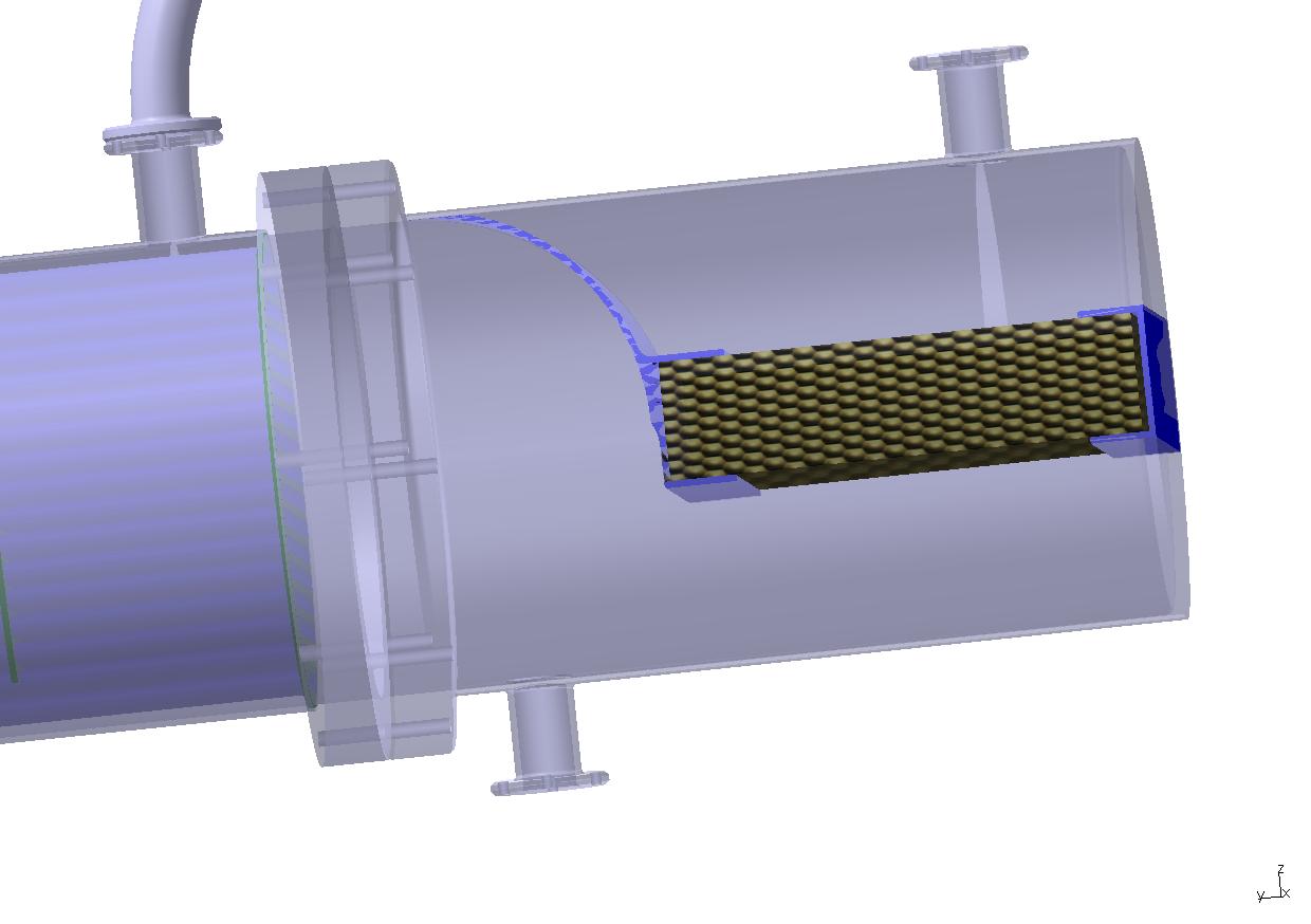
2 Diagram night principle of operation
![]()
![]()
![]()
![]()

![]()
![]()
![]()
![]()
![]()
![]()
![]()
![]()

![]()
![]()
![]()
![]()
![]()
![]()
![]()
![]()
![]()
![]()
![]()
![]()
![]()


![]()
![]()

![]()


![]()

![]()


![]()
![]()
![]()
![]()
![]()
![]()
![]()
![]()
![]()
![]()
![]()
![]()


![]()
Considering the price of the panels with cell photo voltaic this principle of operation will be reserved for small installation, if we wish of greater production,
it will be more advantageous to use the first installation describes previously (former file May 2003).
Compared to the first calculations of the STANDARD engine II, for an electric production of 400 KW, It was possible to produce 2,5 tons of water/day.
By using a simple rule of three, we can have a first global solution allowing to define the electric need allowing to produce 50 liters of water/day:
400 kW / 2500 liters) x 50 = 8 kW (for 5 hours)
If we take the average price of photovoltaic electric production of 6€ /watt with 3 hours of autonomy, That makes the price of the electric need for the installation with:
((8 000 w x 6€ )/3hours) x 5 hours = 80 000 €
The average lifespan of a voltaic installation turns around 25 years.
If we consider the production of water on 20 years:
50 liters x 360 x 20 = 360000 liters of water
if we use the financial requirement in electricity to determine the price of the liter of water that gives:
80 000 € / 360000 = 0,22 € / liter, that is to say approximately 1,20 F/liter
In this price It is not included the price of the mechanical part of the installation.
Another approach consists in identifying the useful work of the installation by affecting a total output to it:
We wish to vary the enthalpy of the air of 38 kJ/kg with 27 kJ/kg with a flow of 0,35 Kg/s
Of where useful work will be of: (38 - 27) X 0,694 = 7, 634 kJ/s is 7634 W optimized work
Without optimization,
we wish to vary the enthalpy of 38 kJ/kg with 13kj/kg with a flow of 0,35 Kg/s
Of where a useful work of: (38 - 13) X 0,694 = 17,35 kJ/s is 17350W
Pu/Pa = ![]() if we fix the output à.70% respectively, in each case we obtain:
if we fix the output à.70% respectively, in each case we obtain:
Pa=Pu / ![]() =>
7634 / 0,7 = 10905 w => ((10905 x 6 / 3) 5) / 360000 = 0,302 € that is to
say1 ,96
F/liter
=>
7634 / 0,7 = 10905 w => ((10905 x 6 / 3) 5) / 360000 = 0,302 € that is to
say1 ,96
F/liter
and 17350 / 0,7 = 24785 w=> ((24785 x 6 / 3) 5) / 360000 = 0,688 € that is to say 4 ,47 F/liter (1€ = 6,5F)
This approach is not to optimize:
Our installation has need to function: of a ventilator, of a water pump (or a system of thermo siphon), of voltaic panel, an inverter allowing the electric adaptation between the production continues and of the alternate engines, ventilator and pump, and of accumulator or dry battery.
It is possible the private one of the inverter, in this case we will replace the alternate engines by engines with current continues, but then another problem is paused:
An engine with current continuous has in its components of the brushes making it possible to establish contacts with the armature. These brushes wear, and by this fact the MTBF (average time without breakdown) of the whole of the installation decreases.
The consumption of the water pump is ridiculous compared to the need for the ventilator:
the pump is only used to ensure the circulation of the glycol- water of where one of the objectives will be to pay attention not to create a height of potential water (to be overcome) in the circulation of the glycol- water of the installation.
One of the prime objectives will be to bring back the electric need to requirement in a consumption 10 times lower for preceding calculation,
which will make it possible to have an average price of the liter of water more cohérant with reality, and will allow us to integrate a budget for the mechanical needs.
We will fix the price of the liter of water at 0, 022€ (either 0,12f) what will translate the budgetary resources for electric consumption,
this one being a variable cost with one lifespan 25 years, whereas the price of the condenser and radiant panel belong to the fixed cost,
with one high lifespan.
The electric output of the ventilator is a function of the requirement in air flow (M3/s) for the its electric output and pressure loss for the aeraulic network.
The financial potential can be deduced from it and thus to deduce total consumption from the installation which is a function primarily of the consumption of the ventilator:
800W x 6€ / 3h x 5h = 8000€
A number of liters of water produced: 50 liters X 365 days X 20 years = 365000 Liters.
Resources: 365000 X 0,022€ = 8030€ (round-off with 8000€)
The approximate price of voltaic Watt being of 6€ for 3 hours of uses,
Our need being 5 hours of use, Following a rule of three, we obtain: (((8000€ X 5 H) = 800W
Our will setting thus take, like with availability of electric output 800 W - 20 % auxiliary food more pump (value which will be estimated thereafter) - the output of the ventilator (we will take 80%)
What remains us:
Pu = ![]() with
with
![]() fixed
at 0,8
fixed
at 0,8
(800w
– 20%)![]() =
512 W useful
=
512 W useful
The equation of calculation of the useful output ventilator can be written:
![]()
P in watt
![]() in
M
in
M![]()
![]() in Pa
in Pa
of where according to flow, we can determine of it the maximum pressure loss tolerated
to keep a price of the liter of reasonable water: (knowing that this pressure loss is a function of the flow)

Climatic starting condition:
Temperature day labourer: 35°C with 25%
with an average variation of temperature enters the day and the night of 20°C
of where per deduction, a night temperature of 15°C to 80 % of moisture.
It will be appreciable d?éviter the appearance of freezes in the condenser, that could decrease the air flow and this fact of stopping
the operation of the installation.
By safety we will take a temperature air left condenser 2°C.
What will be translated according to the diagram of Molier by (9 - 5) grams of water/kg of air.
![]() (function of the pressure and the temperature)
(function of the pressure and the temperature)
a production of 50 kilos eau/5heures = > 10kg/3600s = 0,0027 KG is 2,7 grams/s
2,7 / 4 that is to say 0,694 Kg of air/s or 0,694/1,292 = 0,537 M3/s
![]() of where the pressure loss max
of where the pressure loss max
having to be of 512 W / 0,537 M3/s= 9,53mbar
Being given (to be checked) that the pressure loss of separator
will be assembled in series on the circuit of air making it possible to recover the water droplets, this one having a pressure loss
fixed at 5 mbars (to be checked)
We deduce from it that the maximum pressure loss of the condenser will be 4 mbar.
Knowing the air flow useful for the requirement out of water,
the challenge will be to dimension the condenser by minimizing its pressure loss.
Note: It is useless to indicate that the price of manufacture of a prototype one largely higher at a price of the same product in series. Moreover manufacture d?un condenser belongs to the know-how of the manufacturer, bus in spite of the efforts of the physicists, the calculation of dimensioning remains still relatively empirical.
Following calculations are carried out with Excel, their allowing an interactivity.
The step consists in fixing the limiting conditions and to approach the operating conditions.
We are in possession of an estimate of a company, but as it is known as previously and justified,
a total dimensioning was joined to us to an estimate answering itself an expression of need,
calculations remain confidential. But that will enable us to save time.
Herewith the expression of need:
| Driving project with renewable energy | ||||||||
| Characteristic necessary of the condenser | ||||||||
| objective: | to extract 2,7 g/s from distilled water | |||||||
|
||||||||
| (+273) | ||||||||
| Temperature input air | Te | 15 | °C | soit: | 288 | °K | ||
| Temperature output air | Ts | 3 | °C | soit: | 276 | °K | ||
| Temperature input water glycol | te | -3 | °C | soit: | 270 | °K | ||
| température output water glycol | ts | 2 | °C | soit: | 275 | °K | ||
| Specific heat air | C | 1006 | j/kg.°k | |||||
| Specific heat water | c | 4180 | j/kg.°k | |||||
| water + 10% glycol | c' | 4000 | j/kg.°k | |||||
| water + 30% glycol | c'' | ? | j/kg.°k | |||||
| flow air according to the requirements in water taking away | 0,694 | Kg/s | ||||||
| flow glycolée water (deduced for glycolée water with 10%): | 0,42 | Kg/s | ||||||
| pressure loss circuit air, wished (by including the separator): | 9 | mbars | ||||||
| question: | ||||||||
| dimensioning: | ||||||||
| pressure loss circuit water in equivalence in water column (M) : | ? | |||||||
| diameter of the circuit of air: | ? | |||||||
| price: | ||||||||
| With the unit | ? | |||||||
| Exemplary percent/month: | ? | |||||||
| Delivery periods after order: | ? | |||||||
| Cordialement, | ||||||||
| Le jeudi 13 novembre 2003, | ||||||||
| Jean-Michel BAËS | ||||||||
| site perso: http://solar.energy.free.fr | ||||||||
After a first difficulty of with the risk of freezes, the choice of the type of condenser at appointed summer:
It will be a condenser with Co-current.
The values in heavy type blacks, are to be informed.
The values in red characters are calculated.
1) calculation of the NUT and the DTLM (allowing a redundancy of calculation).
2) To impose dimensions of the tubes their spacings, volumes.
3) To check the REYNOLDS circuit air.
4) To re-examine if necessary dimensions circuit air with an aim of obtaining a REYNOLDS close to 20000.
5) To check the REYNOLDS circuit water: possibility of correcting the number of partition,
or of modifying the water flow (which itself will modify the temperature entry water condenser).
6) To calculate the number of NUSSELT.
7) To calculate the conductance K
- Two methods of approach result:
With the number of NUT: to calculate the heat-transferring surface
With the DTLM: To calculate the heat-transferring surface
8) Calculation pressure loss circuit air.
9) Dimensioning circuit of the radiant panel (with data obtained with MATLAB to see 4.2 dimensioning radiative panel).
10) In first approach will calculate we it with the DTLM (Thereafter it will be possible for us according to an assumption (to be checked) that the solid behaves like a liquid in evaporation).
11)Calculation pressure loss circuit water
(with the front share, it will be necessary to dimension the radiant panel enabling us to know its induced pressure loss and to summon it with that of the condenser)
|
|
|
|
|
|
|
|
|
|
|||
|
|
|
|
|
|
|
|
|
|
|||
|
|
|
|
|
|
|
|
|
|
|||
|
|
|
|
|
|
|
|
|
|
|||
|
|
|
|
|
|
|
|
|
|
|||
|
|
|
|
|
|
|
|
|
|
|
|
|
|
|
|
|
|
|
|
|
|
revision of the temperature entry water condenser, according to the water flow, allowing to obtain a better Reynolds: |
|
|
|||||
|
|
|
|
||||||
|
|
|
|
|
|
|
|
|
|
|
|
if flow water = |
0,42 |
Kg/s |
|
|
|
|
|
|
|
if temperature of exit water condenser = temperature left air - 1°C |
|
|
|||||
|
|
.= |
275 |
°K |
|
|
|
|
|
|
|
Of where temperature entry water: te = ts - (MC/mc) x (Te - Ts) |
|
|
|
||||
|
|
.= |
269,519906 |
°K |
.=> |
-3,48009419 |
°C |
|
|
|
|
|
|
|
|
|
|
|
|
|
|
to recompute the nut with the new inlet temperature: |
|
|
|
|
|||
|
|
Calculation of the need for flow water, dimensioning radiant panel, condenser, |
|
|||||
|
|
Limiting characteristics, conditions |
|
|||||
|
1 |
Variables |
|
|
|
|
||
|
2 |
Temperature of the point of rosy |
Tr |
12,5 |
°C |
285,5 |
°K |
|
|
3 |
|
|
|
|
|
|
|
|
4 |
|
Heat |
Cold |
|
|
|
|
|
5 |
Temperature in general |
T |
t |
|
|
|
|
|
6 |
Inlet temperature |
Te |
te |
|
|
|
|
|
7 |
Temperature of exit |
Ts |
ts |
|
|
|
|
|
8 |
Mass throughputs |
C |
c |
|
|
|
|
|
9 |
Coefficients of conduction |
H |
h |
|
|
|
|
|
10 |
|
0 |
° K = |
-273 |
°C |
|
|
|
11 |
|
|
PI = |
3,14 |
|
|
|
|
12 |
Temperature entry air |
Te |
15 |
°C |
288 |
°K |
|
|
13 |
Temperature left air |
Ts |
3 |
°C |
276 |
°K |
|
|
14 |
Temperature entry glycol |
te |
-3,4801 |
°C |
269,52 |
°K |
|
|
15 |
temperature left glycol |
ts |
2 |
°C |
275 |
°K |
|
|
16 |
°K of temperature of pinching numbers left = |
1 |
°K |
|
|
|
|
|
17 |
Specific heat air |
C |
1006 |
j/kg.°k |
|
|
|
|
18 |
Specific heat water |
Ce |
4180 |
j/kg.°k |
|
|
|
|
19 |
Specific heat water (30%) |
c |
3640 |
j/kg.°k |
|
|
|
|
20 |
Specific heat stainless: |
Ci |
500 |
j/kg.°k |
|
|
|
|
21 |
water+ 10% glycol=>c =4000 |
|
|
|
|
|
|
|
22 |
Thermal conductivity of the air (lambda or k) |
|
0,02 |
W.M^ -1.K^ -1 |
|
|
|
|
23 |
Thermal conductivity of water (lambda or k) |
|
0,56 |
W.M^ -1.K^ -1 |
|
|
|
|
24 |
Thickness of the wall |
e |
0,002 |
M |
|
|
|
|
|
Thermal conductivity of stainless (lambda or k) |
|
15 |
W.M^ -1.K^ -1 |
|
|
|
|
26 |
index of roughness |
0,000001 |
M |
|
|
|
|
|
27 |
Primary circuit |
|
|||||
|
28 |
Flow air according to the requirements in water taking away: M = |
0,694 |
Kg/s |
|
|
|
|
|
29 |
density of the air (ro): |
1,292 |
Kg/M3 |
|
|
|
|
|
30 |
Of where flow: Dv = Mair/ro= |
0,5371517 |
M3/s |
|
|
|
|
|
31 |
Kinematic viscosity coefficient of the air(20°c): v(air) = |
0,0000156 |
M^2/s |
|
|
|
|
|
32 |
dynamic coefficient mu = ro(air) x v(air) = |
2,0155E-05 |
kg/m.s |
|
|
|
|
|
33 |
Gr. water numbers/ kg air : ngr = |
9 |
g/kg |
|
|
|
|
|
34 |
Water flow contained in the air Me = (nkgr water X Mair) = |
0,004858 |
kg/s |
|
|
|
|
|
35 |
average density of the water vapor (ro) = to n(kgeau/kgair) X ro air = |
0,009044 |
Kg/M^3 |
ro de l'air? |
|
||
|
36 |
Of where flow: Dv = Dvapeur/ro |
0,5371517 |
M3/s |
|
|
|
|
|
37 |
a number of average kg of water per kg of air |
0,007 |
nombre de Kgeau par kgair |
|
|||
|
38 |
Kinematic viscosity coefficient average to 10°C: v(water) = |
0,0000013 |
M^2/s |
|
|
|
|
|
39 |
dynamic viscosity coefficient driven = ro(water) X v(water) = |
1,1757E-08 |
kg/m.s |
|
|
|
|
|
40 |
|
|
|
|
|
|
|
|
41 |
secondary circuit |
|
|||||
|
42 |
MC(Te - Ts) =mc (ts - te) |
|
|
|
|
|
|
|
43 |
of where water flow: |
|
|
|
|
|
|
|
44 |
(MC(Te - Ts)) / (c(ts-te)) = m= |
0,42 |
Kg/s |
débit eau |
|
|
|
|
45 |
density of water(ro): |
1000 |
Kg/M3 |
|
|
|
|
|
46 |
of where water flow: Dv =Meau/ro = |
0,00042 |
M3/s |
|
|
|
|
|
47 |
Kinematic viscosity coefficient to 0°C: v(water) = |
0,0000015 |
M^2/s |
|
|
|
|
|
48 |
dynamic viscosity coefficient driven = ro(water) X v(water) = |
0,0015 |
kg/m.s |
|
|
|
|
|
50 |
calculation of the NUT and the DTLM |
|||||
|
51 |
difference in temperature average logarithmic curve (unspecified exchangers) |
|
|
|
|
|
|
52 |
(DTLM ) = ( (Te - ts) - (Ts - te) ) / ln( (Te - ts) / (Ts - te)) = |
9,36 |
°K |
|
|
|
|
53 |
temperature of mixture |
|
|
|
|
|
|
54 |
teta1 = (M x C x Te) + m x c x te) / (M x C + m x c ) = |
275,31 |
°K |
ou |
2,3135 |
°C |
|
55 |
MC =Mair x Cair + Mea Ce = |
698,16 |
J/s.°K |
|
|
|
|
56 |
m x c = |
1528,80 |
J/s.°K |
|
|
|
|
57 |
flow max exchanged for an infinite surface: |
|
|
|
|
|
|
58 |
fimax =MC(Te - teta1) =mc(teta1- te) = |
8857,25 |
8857,3 |
J/s |
|
|
|
59 |
we are if MxC < m x c |
|
|
|
|
|
|
60 |
of where : E = |
|
|
|
|
|
|
61 |
E = (Te - Ts) / ( Te - te) = |
0,65 |
|
|
|
|
|
62 |
R = MC / mc = |
0,46 |
< 1 |
|
|
|
|
63 |
P(brewed) = (ts - te) / (Te - Ts) = |
0,46 |
|
|
|
|
|
64 |
en lecture F = |
0,97 |
|
|
|
|
|
65 |
NUT = (1/ (1 -R) x ln (1- ER) / (1- E) |
1,28 |
|
|
|
|
|
66 |
|
|
|
|
|
|
|
67 |
for E = 0,6 et un R = 0,4 = > F = 0,95 et E = 0,8 et R = 0,10 F = 1 |
|
|
|
|
|
|
68 |
exchanging dimensioning dimensions: |
|||||
|
69 |
Outdistance average between the partitions: Dclmoy = |
0,2 |
M |
|
|
|
|
70 |
A number of tubes circuit air: n = |
203 |
|
|
|
|
|
71 |
Internal diameter: Di = |
14 |
mm |
ou: |
0,014 |
M |
|
72 |
External diameter tubes: De = |
16 |
mm |
ou: |
0,016 |
M |
|
73 |
Diameter condenser: Dext = |
355,6 |
mm |
ou: |
0,3556 |
M |
|
|
thickness condenser =aipc = |
5 |
mm |
ou: |
0,005 |
M |
|
|
Internal diameter condenser: Dint = |
345,6 |
mm |
ou: |
0,3456 |
M |
|
74 |
Between axis: a = |
20 |
mm |
ou: |
0,02 |
M |
|
|
Outdistance between the tubes : da = a - De = da = |
4 |
mm |
ou: |
0,004 |
M |
|
75 |
calculation of the Reynolds number |
|||||
|
76 |
surface hydraulic = PI x Di^2 /4 x numbers of tube = Si = |
0,0312 |
M^2 |
|
|
|
|
77 |
Speed retailer of the air: V(air) = Dv / Si = |
17,1892 |
M/s |
|
|
|
|
78 |
Reynolds number: |
|
|
|
|
|
|
79 |
Air: RE = ro x V x Di / mu = |
15426,18 |
must be >= à 20000 |
|
||
|
80 |
|
|
|
|
|
|
|
81 |
(Speed of the water contained in the air without taking account of the air velocity: V(ea) = Dv/Si = |
17,1892 |
M/s ) |
|
|
|
|
82 |
we will consider that the speed of the water vapor is identical to the air |
|
|
|
|
|
|
83 |
Eau dans air: REa = ro x V x Di / mu = |
185114,16 |
|
|
|
|
|
84 |
(spacing enters tubes X by the maximum number of tubes + the vacuum between the peripheral tubes and diameter of the external tube) X outdistances average between the plates = |
|
|
|
|
|
|
85 |
((Da x16 + 2 x 0,0344M )) x Dclmoy = Smoy = |
0,0266 |
M^2 |
|
|
|
|
88 |
entered diameter condenser (given manufacturer) |
0,04 |
M(DN40) |
|
|
|
|
89 |
Speed retailer of water: V(eau)moy = Dv(water/Smoy) |
0,0158 |
M/s |
|
|
|
|
91 |
water: REmoy = ro x Vmin x Dclmax / mu = |
2108,43 |
|
|
|
|
|
92 |
if the Reynolds number must be higher than 2000 that implies to re-examine the flow and the inlet temperature exchanger: |
2000 |
|
|
|
|
|
93 |
V max = (RE /ro) * mu /Dclmoy = |
0,0150 |
M/s |
|
|
|
|
95 |
Calculation length condenser with the NUT |
|||||
|
96 |
NUT = KFS/MC = > S =(NUT x MC)/K F = |
13,84 |
M^2 |
|
|
|
|
97 |
L = S /(n*PI * Di) = |
1,55 |
M |
|
|
|
|
Calculation of the number of Nusselt |
|||||
|
numbers of Prandtl for the air: |
|
|
|
|
|
|
Pr(air) =( mu x C) / k |
1,0138 |
|
|
|
|
|
numbers of Prandtl for water contained in the air: |
|
|
|
|
|
|
Pr(ea) =( mu x C) / k |
0,0025 |
|
k air ? |
||
|
numbers of Prandtl for water: |
|
|
|
|
|
|
Pr(water) =( mu x C) / k |
9,75 |
|
|
|
|
|
numbers of Nusselt for the air: |
|
|
|
|
|
|
Pr ^0,4 = |
1,01 |
|
|
|
|
|
Re^0,8 = |
2241,85 |
|
|
|
|
|
numbers of Nusselt for the air: Nü1 =0,023 x Re^0,8 x Pr ^0,4 |
51,85 |
|
|
|
|
|
numbers of Nusselt for water: |
|
|
|
|
|
|
Pr ^0,4 = |
2,49 |
|
|
|
|
|
Re^0,8 = |
456,21 |
|
|
|
|
|
numbers of Nusselt for water:Nü2 =0,023 x Re^0,8 x Pr ^0,4 |
26,09 |
|
|
|
|
|
numbers of Nusselt for water contained in the air: |
|
|
|
|
|
|
Pr ^0,4 = |
0,0496 |
|
|
|
|
|
Re^0,8 = |
0,0023 |
|
|
|
|
|
numbers of Nusselt for water contained in the air: Nü3 =0,023 x Re^0,8 x Pr ^0,4 |
2,6499E-06 |
|
|
|
|
|
conductance K: |
|||||
|
1/K = 1/(Hc+Hcwater) + 1/hc +(e/langda_stainless) = > K = |
66,65 |
|
|
|
|
|
coefficient of convectif transfer for the air: |
|
|
|
|
|
|
Nü1 = hc x Di / K= > hc = Nü1 x kair / Di = |
74,07 |
|
|
|
|
|
Nü2 = hc x Di / Kwater= > hc = Nü2 x Kwater / Di = |
730,56 |
|
|
|
|
|
(water in air )Nü3 = Hcwater x Di / K= > Hcwater = Nü3 x kwater / D = |
0,0001 |
|
|
|
|
|
Calculation length condenser with the DTLM |
|||||
|
fi = MC(Te - Ts) = mc(ts - te) = K x F x S ( DTLM) d'où |
|
|
|
|
|
|
S = MC ( Te - Ts) / K F (DTLM) = |
13,84 |
M^2 |
|
|
|
|
L = S / n*PI*Di = |
1,55 |
M |
|
|
|
|
Pressure loss circuit of air: |
|||||
|
Ks/Di = |
7,1429E-05 |
|
|
|
|
|
reading of lamdda water = |
0,011 |
|
|
|
|
|
reading of lamdda air = |
0,0275 |
|
|
|
|
|
V(air)^2 =( DV /PI * Di))^2 |
149,1551 |
M/s |
|
|
|
|
V(ea)^2 =( DV /PI * Di))^2 = |
295,4676 |
M/s |
|
|
|
|
It will be necessary to take into account the pressure loss of the separator. |
|
||||
|
deltaPe = lambda x ro x( V(ea)^2)/2 x L/D = |
1,63 |
pascals |
ou |
1,6E-05 |
bars |
|
deltaP = lambda x ro x( V(air)^2)/2 x L/D |
293,34 |
pascals |
ou |
0,00293 |
bars |
|
|
|
|
|
|
|
|
138 |
Dimensioning radiant panel |
|||||
|
139 |
We will make an approach by the DTLM |
|
|
|
|
|
|
140 |
energy received by natural convection of the radiant panel: |
|
|
|
|
|
|
141 |
There is no natural convection being given that the panel is horizontal. |
|
|
|
|
|
|
142 |
the only convection according to the wind, will be considered null |
|
|
|
|
|
|
143 |
hair = 0,4 x(teta/D)^0,25 |
|
|
|
|
|
|
144 |
Numbers of Nusselt: |
|
|
|
|
|
|
145 |
Water panel RE = ro x V x D / mu = |
11883,57 |
|
|
|
|
|
146 |
speed according to the hydraulic diameter: |
|
|
|
||
|
147 |
vp = withdrawal / Si = |
0,5942 |
M/s |
|
|
|
|
148 |
Pr(water) =( mu x c) / Kwater = |
9,75 |
|
|
|
|
|
149 |
numbers of Nusselt for water Nü =0,023 x Re^0,8 x Pr ^0,4 = |
104,06 |
|
|
|
|
|
150 |
Nü = hc x D / K= > hc = Nü x Keau / D = |
1942,47 |
|
|
|
|
|
151 |
we will neglect e / lambda |
|
|
|
|
|
|
152 |
of where 1/hc = 1/K = > K = |
1942,47 |
|
|
|
|
|
153 |
We will consider that the temperature of the panel will be fairly equal to its temperature of radiation: of where ts =te |
|
|
|
|
|
|
154 |
difference in temperature average logarithmic curve (exchanger Co-current (te = ts = tp) |
|||||
|
155 |
(DTLM ) = ( (Te - tp) - (Ts - tp) ) / ln( (Te - tp ) / (Ts - tp)) |
3,59 |
°K |
|
|
|
|
156 |
fi = mc(Te - Ts) = K x S ( DTLM) d'où |
|
|
|
|
|
|
157 |
S = mc ( Te - Ts) / K (DTLM) = |
6,59 |
M^2 |
|
|
|
|
158 |
L = S / *PI*Di = |
69,89 |
M |
|
|
|
|
159 |
Numbers of tube: n = L / e = |
12 |
|
|
|
|
|
160 |
hydraulic diameter of the water of the radiant panel |
|
|
|
|
|
|
161 |
thickness tubes |
2 |
mm |
.=> |
0,002 |
M |
|
162 |
Di |
30 |
mm |
.=> |
0,03 |
M |
|
163 |
Surface hydraulic Si = PI x Di ^2 /4 x n tub par. = |
706,86 |
mm^2 |
.=> |
0,00071 |
M^2 |
|
164 |
Dext |
34 |
mm |
.=> |
0,034 |
M |
|
165 |
Numbers of tube in parallel |
1 |
|
|
|
|
|
166 |
mc |
1528,8 |
W/°K.s |
|
|
|
|
167 |
te-ts |
5,48 |
°K |
|
|
|
|
168 |
mc x (te - ts) = |
8377,968 |
W/s |
|
|
|
|
169 |
for a temperature of radiation(matlab): tp = |
268 |
°K |
(= ts - 1,5°k pincement) |
||
|
170 |
energy radiated by M^2 (matlab) Em = |
233,9 |
W/M^2 .s |
|
|
|
|
171 |
surface radiant panel: |
|
|
|
|
|
|
172 |
S =mc x (te - ts) / Em |
35,82 |
M^2 |
|
|
|
|
173 |
Dimension with dimensions panel for a square panel: e = S^1/2 |
6,0 |
M |
|
|
|
|
174 |
Surface radiant panel = hydraulic surface of water |
|
|
|
|
|
|
175 |
Even surface radiated by the tubes them (we will simplify by taking the diameter external with the place of less than one semicircumference) |
|||||
|
176 |
n*Dext = |
0,3971 |
M |
|
|
|
|
177 |
summon small with dimensions wing |
|
|
|
|
|
|
178 |
e - n*Dext = |
5,59 |
M |
|
|
|
|
179 |
(2 ailettes / tube) =>((n*Dext-e)/n)/2 = dimail = |
0,2392 |
M |
|
|
|
|
180 |
Pressure loss circuit of water |
|||||
|
181 |
Pressure loss circuit of water radiant panel |
|
|
|
|
|
|
182 |
Ks/Di = |
3,3333E-05 |
|
|
|
|
|
183 |
reading of lambda = |
0,018 |
|
|
|
|
|
184 |
V(eau)^2 = |
0,3530 |
M/s |
|
|
|
|
185 |
deltaP = lambda x ro x( V(air)^2)/2 x L/D |
7402,56344 |
pascals |
ou |
0,07403 |
bars |
|
186 |
Pressure loss circuit of water minimum condenser |
|
|
|
|
|
|
188 |
reading of lambda = 64/Re = |
0,03035429 |
|
|
|
|
|
189 |
V(water_max)^2 = |
0,0003 |
M/s |
|
|
|
|
190 |
L = 8 X Diameter of the condenser, D = distance enters the partitions |
|
|
|
|
|
|
191 |
deltaP = lambda x ro x( V(eau)^2)/2 x (Dint x 8)/Dclmoy |
52,4646 |
pascals |
ou |
0,00052 |
bars |
|
192 |
Calculation mud of expansion |
|||||
|
193 |
volume of water of the hydraulic system: |
|
|
|
|
|
|
194 |
condenser: |
|
|
|
|
|
|
195 |
((Dext^2 x Pi)/4) x L) - ((n x(De^2 x PI)/4) x L) = VC = |
0,09066498 |
M^3 |
|
|
|
|
196 |
panel: |
|
|
|
|
|
|
197 |
(Di^2 x PI)/4 x e x n + (Di^2 x PI)/4 x ( PI x dimail) x ( n -1) = VP = |
0,05507674 |
M^3 |
|
|
|
|
198 |
piping: |
|
|
|
|
|
|
199 |
diameter: DT = |
40 |
mm |
.=> |
0,04 |
M |
|
200 |
Longueur: LT = |
|
|
|
6 |
M |
|
201 |
of where: VT = DT^2 x PI /4 x LT = |
0,00753982 |
M^3 |
|
|
|
|
202 |
Vtotal =VC + VP + VT = Vtotal = |
0,15328154 |
M^3 |
.=> |
153,282 |
Litres |
|
203 |
We will arbitrarily fix the pressure of operation at: P2 = |
2 |
bars |
|
|
|
|
204 |
Atmospheric pressure:P1 = |
1 |
bars |
|
|
|
|
205 |
Coefficient of extension of water: n = |
0,5 |
|
|
|
|
|
206 |
Vtotal <= 300 liters => : |
|
|
|
|
|
|
207 |
Vn = 3 +( n x VE x (P1 / P1 + P2) = |
28,5469231 |
Litres |
.=> |
0,02855 |
M^3 |
|
208 |
dimensioning: l = |
0,3 |
M |
|
|
|
|
209 |
Sexpans =Vn / l |
0,09515641 |
M^2 |
|
|
|
|
210 |
Dexpans= (4 x Sexpans /PI)^0,5 = |
0,348076 |
M |
|
|
|

m : mass throughput of water = ?
c : Specific heat of water-glycol = 3640 j/kg.°k
ts :temperature left water= 2°C (275°k)
te : temperature entry of water = -3°C (270°k)
Of where water flow: ![]() = 0,46 Kg/s in first it approaches however will be possible
to optimize the temperature entry water according to its Reynolds number.
= 0,46 Kg/s in first it approaches however will be possible
to optimize the temperature entry water according to its Reynolds number.
of where power pumps:
![]()
![]() useful output (W)
useful output (W)
![]() flow(M
flow(M![]() )
)
![]() Voluminal energy or pressure loss of the hydraulic
network expressed in M we will take 10M = 1bar
Voluminal energy or pressure loss of the hydraulic
network expressed in M we will take 10M = 1bar
of where 30 mbar = 0, 03 by operational safety let us calculate with1M or 0,1 bars
P =0,46 /1000 x 1 x 9810 = 4.51 W
Pa =![]() (
(![]() = 0,6) = > Pa = 7.52 W
= 0,6) = > Pa = 7.52 W
That confirms that the consumption of the pump is negligible in front of that of the ventilator.
![]()
![]() :radiated energy
:radiated energy
![]() : emissivity (0<
: emissivity (0<![]() <1) according to materials
<1) according to materials
![]() :constant of Stephan boltmann (5,67
:constant of Stephan boltmann (5,67![]() 10
10![]() W.M
W.M![]() .K
.K![]() )
)
![]() : surface radiating
: surface radiating
![]() : temperature of the hot body
: temperature of the hot body
![]() :
temperature of the cold body
:
temperature of the cold body
radiative panel
![]()
![]()

![]()
![]()
![]()
![]()

Delta Hair x flow water = Delta Heau x flow water (with the ready output of the condenser fixed at80%)
D’où ![]() = Delta Hair x flow air / output condenser
= Delta Hair x flow air / output condenser
![]() = (1006 (288-276) x 0,694 )/0,8 = 10472 W
= (1006 (288-276) x 0,694 )/0,8 = 10472 W
with ![]() =0,8
=0,8
Temperature of the sky (cold source= - 50°C (223°K)
We will take Tc v = average value between te and ts: (ts - te)/2 + te = 272,5
![]() =
= ![]() / (
/ (![]() ) =>10472 / (0,8 x 5,67 .10
) =>10472 / (0,8 x 5,67 .10![]() x ( 272,5
x ( 272,5![]() - 223
- 223![]() )
)
= 10472 / 4,536.10![]()
![]() 3 ,041017223.10
3 ,041017223.10![]()
= 10472/ 137,94= 75,91 M![]() (surface average)
(surface average)
As an indication:
surface higher size
for TC = 275°K = >![]() min= 71,11 M
min= 71,11 M![]()
for TC = 270°K =>![]() max= 81,24 M
max= 81,24 M![]()
if we make ((![]() max -
max - ![]() min) / 2) +
min) / 2) +![]() min = 76,26 M
min = 76,26 M![]()
On the other hand, it will be desirable to know with precision the temperature of the sky!
The temperature of the night sky in very high altitude (850 km) is close to 4°K source to check.
It is necessary to evaluate the heat-transferring surface between the aerial element and the sky:
Energy radiated of an element on the night sky:
(bibliography 7.1)

To calculate the energy radiated by the sky on an element
of dimension e![]() M^2 à une température T1 = 2°C
M^2 à une température T1 = 2°C
Knowing that:
the average temperature of the sky of 4°K at an altitude which we will fix X = 850 km
Ray of the ground: ![]() = 6278 Km
= 6278 Km
The terrestrial element e undergoes the radiation of the sky + energy by natural convection.
We will be interested for the moment in radiated energy :
- While taking as assumption that the emissivity of the element E is identical to the emissivity of the sky(0,8)
- The equation of the energy radiated by the element is related to its temperature:
![]()
![]() energy radiated in W
energy radiated in W
0<![]() < 1 coefficient of emissivity
< 1 coefficient of emissivity
![]() Constant of Stéphan Boltmann 5,67.10^-8W.M^-2.°K^-1
Constant of Stéphan Boltmann 5,67.10^-8W.M^-2.°K^-1
Se radiant surface (M^2
Te temperature of the element in °K
The radiated energy of the sky:
![]()
Sc being the surface of the sky
Tc the temperature of the sky
![]() the emissivity of the sky (near to 1)
the emissivity of the sky (near to 1)
Of where the energy exchanged by radiation between the element and the sky is:
![]() => d’où :
=> d’où : ![]() =
= ![]()
Let us calculate the surface of the sky: (sky = ciel, ground = terre)

Let us pose:
![]()
K = ![]()
The angle swept by the aerial element of the sky will be
along axis X: ![]()
The angle swept by the aerial element of the sky will be
along the axis y: ![]()
Of where the new equation will be:

Let us calculate the value of![]() :
:
X = altitude where the temperature = 4°K
![]() d’où
d’où ![]()
![]() =
= ![]()
si e =10M
![]() => n =
=> n = ![]()
![]() => m =
=> m = ![]()
of where the number of aerial element of the sky =![]() =
=![]()
![]()
avec :
M : mass throughput of the air = 0,694 Kg/s
C :Specific heat of the air = 1006 j/kg.°k
Te : temperature entry of the air = 15°C (288°K)
Ts : Temperature left the air= 3°C (276°K)
Transposition programs MATLAB of them:
%constantes
R1 =1; %rayon de la terre en M (6378km)
alt= 850; %altitude en M à 4°K
e =1; %en M à l origine, mais pour des problèmes de quantité d'élément à programmer : en KM
PI = 4*atan(1);
Tc = 4; %°K température du ciel
Te = 269.5; %°K température de l'élément
epsilon =0.8;
K =5.67*10^-8*10^6;%W.M^-2.°K-1(*10^6 pour avoir des km^-2
R =epsilon*K;
%variables
R2 =(((R1+alt)^2)-(R1^2))^(1/2); %rayon du ciel à 4°K
nmax = (PI*R2)/e;
nm =floor(nmax);
sinn=zeros(nm,nm);
sinm=zeros (nm,nm);
M=zeros (nm,nm);
P=zeros(1,nm);
S=0;
%création 1ere ligne, 1ere colonne
for x=(1:nm)
sinn(1,x)=(sin((x*e)/R2))*e*(Tc^2);
sinm(x,1)=(sin((x*e)/R2))*e*(Tc^2);
end
for x=(1:nm)
M(1,x+1)=sinn(1,x);
M(x+1,1)=sinm(x,1);
end
%remplissage tableau correspondant au valeur de chaque élément en fonction de leur position géographique
for z =(1:nm)
for y=(1:nm)
M(z+1,y+1)=M(1,y+1).*M(z+1,1);
end
end
N = (e^2)*Te^4;
for u=(1:nm)
for t=(1:nm)
P(1,u)=P(1,u)+M(2,t+1);
end
end
for v=(1:nm)
S=S+P(1,v);%résultat sommation des éléments du tableau
end
Q=R*(N-S);% avec constant en km^-2
QM=Q*10^-6;% avec constante en M^-2
Note:
IT appears as changing the diameter of the ground the number of element decreases without affecting the result For problems of size of a number we will work in km, then we will transpose the results in M. for a precision to 2 digits after the comma, which we take 200Km or 850Km, the computing times differ, but the results are identical.
By this method the power of radiation obtained in M^2 is divided by 2, compared with the results obtained by using an average temperature of -50°C, and by taking the surface of the element.
1) Condenser:
a) primary circuit (air)::
- the pressure loss:
We neglected the losses of flow in entry primary condenser circuit.
If it proves to be impossible to find a ventilator meeting the need for pressure loss, or although this one has an excessive price, we can increase the diameter external of the condenser, in the objective to decrease the length while preserving the heat-transferring surface.
That will cause to increase the number of tubes.
It is necessary to know, by observing the characteristics ventilators, that the capacity to overcome the pressure loss increases with its diameter, however the price of the condenser will also increase with the number of tubes.
The Reynolds number having to meet a need for turbulent fluid, It will be possible also to decrease the hydraulic diameter In short, It will be necessary to make calculations by iteration to manage to meet the requirement in term for cost ventilator,
cost condenser, cost power consumption ventilator.
b) secondary circuit (water):
Being given that we have an inlet temperature negative water (in degree Celsius),
in spite of reduced effectiveness than a condenser to against current, it will be selected a mode of circulation to Co-current, with an aim of avoiding the risks of freezes.
Conductance estimated with the fall:
It is difficult to estimate the Reynolds number, since the tubes of air are perpendicular within the meaning of circulation of water.
For a first approach we considered the distance between the partitions,
which enabled us to estimate the conductance, and by this fact, the heat-transferring surface.
The Reynolds number circuit water being intuitively lower than the actual value, the heat-transferring surface was oversize,
which will make only more effective the condenser.
However being given the weak estimated Reynolds, the pressure loss circuit water condenser at summer under evaluated,
which enables us to evaluate that briefly the power necessary of the water pump.
This power could be to really estimate by experimentation.
2) Radiant panel:
It will be necessary to apply a anti-radiation screen to the inferior part of the panel solving the terrestrial problem of radiation thus.
For an optimal conduction or a good distribution of heat exchange,
It will be preferable to have a similar heat-transferring surface between the tubes/panel and the panel/radiant surface,
thus supporting a good conduction.
approximation of the panel radiation:
The calculation of the radiation was approximated by neglecting the contributions convectifs (primarily at the speed of the wind) absorptions of to the clouds, informellement it was tell to me that this absorption could modify the radiated energy of 50%,
But in our application the presence of cloud is done rare!
Suggestion of calculation:
By analogy with would traditional calculations of convectif exchange, be it possible to identify the mass throughput of the radiant panel,
by considering the mass of the panel, its specific heat, its operating temperature,
and to consider the variation in temperature of the mass throughput null, as if the solid had the properties of a liquid in phase shift?
That will enable us to know the mass of the panel, and to deduce its thickness from it. (On standby of answer)
3) Mud of expansion:
We overestimated the pressure loss circuit water, thus allowing us to dimension the volume of the mud of expansion.
4) Separator:
Its function lies in the need to retain taste them water avoiding thus that they return in the atmosphere,
with a economic constraint consisting in producing only one weak pressure loss:
currently my only source of information comes from a manufacturer of Condenser estimating this pressure loss at 5 mbars.
What it is necessary to know about this artificial water, it is that it with its cycle of life, and that consequently according to its management,
it can have several uses before returning water vapor:
example:
Hygiene -> agriculture -> water vapor
Drinking water -> agriculture -> water vapor
water Food -> agriculture-> water vapor
drink. power station of purification. . water potable.hygiene. with a part in evaporation food
But also:
![]()
![]()
![]()
Drinking water -> drink -> power station of purification -> Drinking water
-> hygiène -> with a part in evaporation
-> food
With the result that progressively production, we increase overall accessibility with the users with the resource which is water.


|
Solar motor TYPE III |
|
 |
|
|
INDEX |
|


